IMPORTANT Make sure that your power supply connections are made to the PCB before powering up the device or you will blow the chip. Personally I would prefer to use a small 24 Volt transformer and a small bridge rectifier for the 24V supply but it is a small convenient way of supplying 24V, but far better if you can manage to get hold of a 12V RF relay.
This is a very good solution for switching 24 Volt relays on from a 12 volts supply line or even down as low as 5 Volts,, I have personally tried several circuits to do this job and failed miserably but this little circuit switches any of the high current 24 to 26 volt relays in with a good clunk of the realy contacts. The output volts can be adjusted by altering just a couple of resister values R1 and R2. These values are worked out from a little calculation from the data sheet below. You must use ECR resistors and capacitors and also an ECR inductor or you will run into problems.
Reading the data sheet you need a 4 layer board but I designed a board layout using just the normal 2 layers and had no problems at all. The chip used is an Radio Spares LM2733 which will handle 1 Amp. The part number is 533-5424.
Important If you use these circuits with a power Supply that is sitting at say between 5 to 12 volts and then switch on the circuit you will not have a problem but however if you switch the power supply onto the board from the off state,, as the power supply is quickly going up in voltage the little LM2733 WILL DRAW enough current to blow the device even though the 24 Volt relay is connected.
I have totally tamed this circuit now however by using a Thyristor and it doesn’t matter now, if you switch the 12 Volts onto the circuit with a relay on the output as the Buck Booster circuit is perfectly safe. I have tested the circuit for days on end and now perfectly safe to use without any worries of blowing up the chip. I have actually blown up about 4 of these devices while in development, but that’s electronic development for you as it doesn’t always work out at the first few attempts.
The PDF files of the PCB and the layout are below, just magnify the board layout to see where the parts go.
I designed the board originally in the Eagle CAD program but now have a CNC Cutting machine so design all of my printed circuit boards in 2D Design and then connect my laptop up to the CNC Machine and let the machine make the PCB
printed circuit board while I go for a walk, no more hazardous chemicals like Ferric Chloride, Sodium Hydroxide to do the developing of the board after the light box stage. Also it can be a bit hit and miss using expensive Photo Resist board at probably £10 an A4 sheet size.


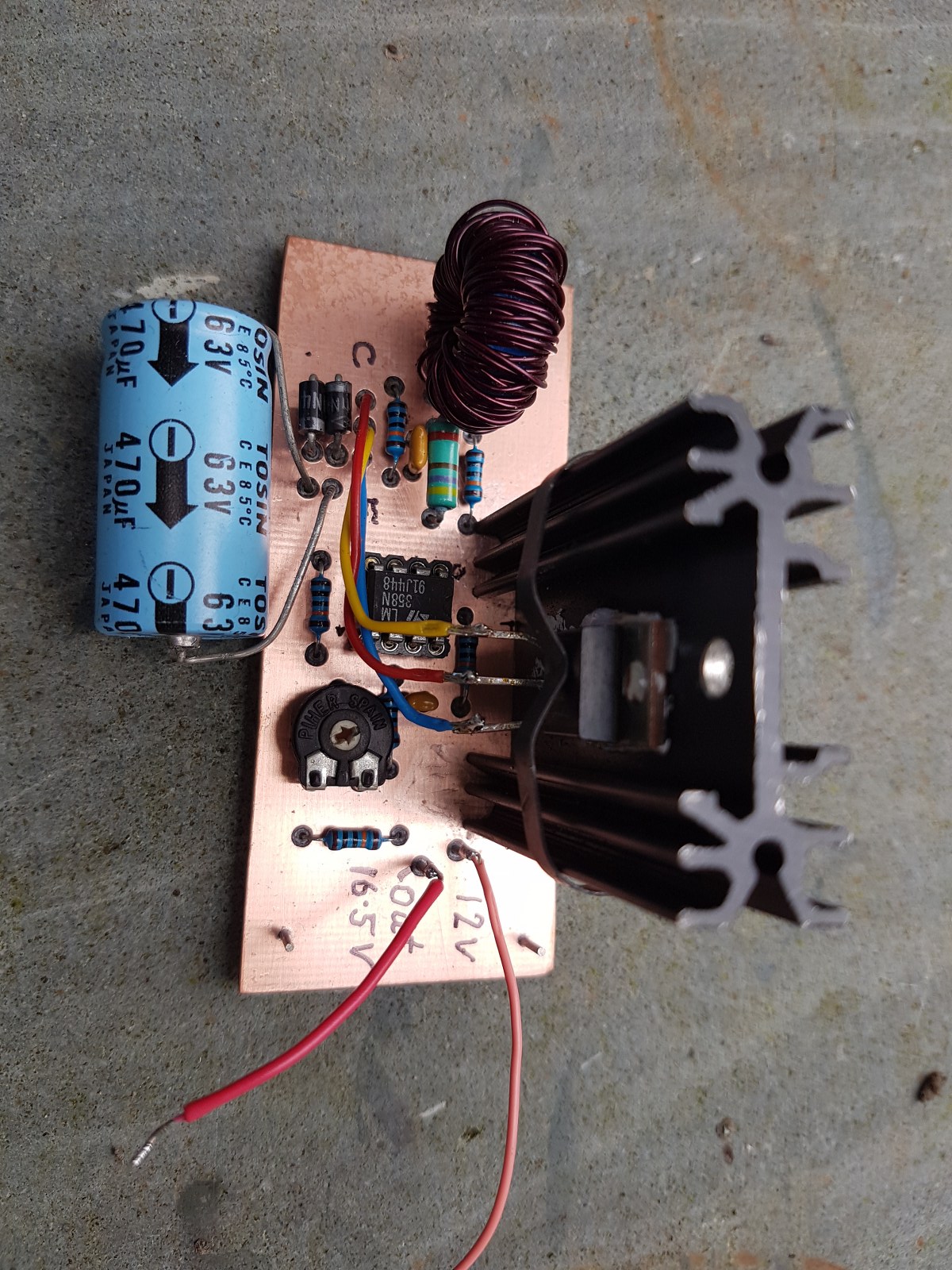
Here is another circuit that works well which again produces 24 Volts from 12 Volts DC at up to 1 Amp. The toroid I used has 150 turns of wire on it which gives me 180uH.
I personally prefer the Buck Booster Texas Instruments chip LM27313.

Here are a couple of printed circuit boards that I produced using my CNC Machine so that you can see how powerful they really are once you have mastered driving the machine.


